This article follows a talk I gave at the Forum International de la Cybersécurité (FIC). After my presentation, a large number of people asked me to publish a detailed article on the subject. That’s one of the reasons I created this blog: to share my research and findings in a way that’s accessible to everyone.
In this article I will present several vulnerabilities that affected many security cameras; notably cases of 0-click code execution, whether via the network or… through the air (yes, really — without sending anything at all).
Vulnerabilities still activeDespite my follow-ups and the discovery that several “white-branded” cameras come from the same manufacturer, these vulnerabilities remain active. This article is by no means an exploitation tutorial. I disclaim all responsibility for malicious use or any damage caused.
This analysis is divided into two parts to make it easier to read and to keep a clear approach:
These two articles do not claim to cover every aspect of the analysis. Some notions may remain partial or require further clarification. That’s why additional complementary content, notably Pentest IoT 101 series, is available to deepen certain concepts and techniques.
Discover how to ...
This first article is not a prerequisite for reading the second, but it provides essential context to better understand the technical analysis that will follow.
Let’s be honest: today, who doesn’t have at least one connected object at home? Between the smartwatch, the voice assistant or the little surveillance camera, these gadgets have settled into our homes almost without us noticing.
One day I needed a Wi-Fi connected surveillance camera. No way I was going to spend €300 on a “pro” solution, so I opted for an “all-in” camera — like the ones you find in stores or homes. I bought two; when configuring them I discovered you had to pay a subscription to access the images remotely. True to my habits, I wanted to take a look “under the hood” to redirect the streams elsewhere… and that’s where I made some rather surprising discoveries.
As mentioned above, I bought two cameras. One on eBay for a handful of euros (€30) and the other at a very, very well-known discount hypermarket in Europe (not naming it — Action) for €60. The two cameras behave quite similarly and cover the same needs — and apparently… they are successful! Lots of people buy these things, so they must be good quality, right?
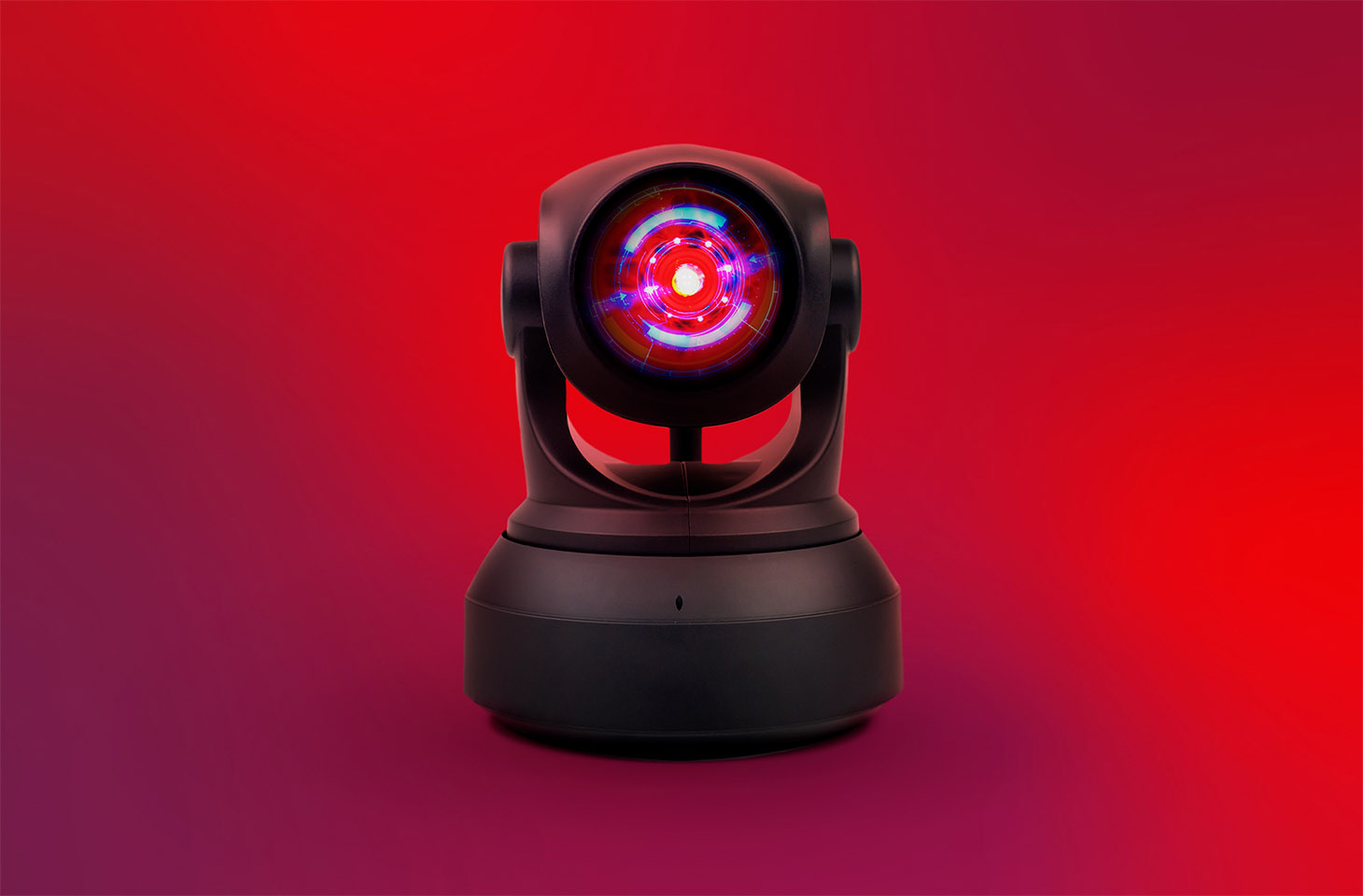
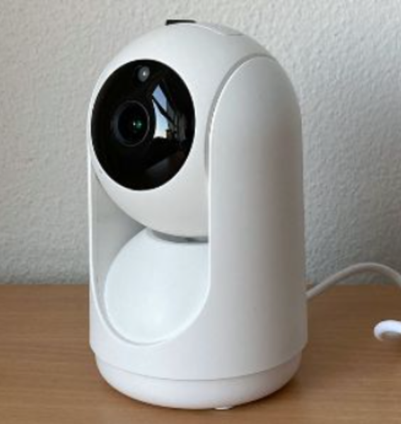 Figure 1 : LSC PTZ Camera
 Figure 2 : Yi IoT
Like most connected devices that handle images (cameras, baby monitors, intercoms, etc.), they typically run a small Linux distribution — for reasons of cost, productivity and development ease.
Imagine it as a slimmed-down Raspberry Pi: powerful enough to run drivers, manage sensors and transmit data, but without a GPU, with far less RAM and none of the components that are too power-hungry or expensive. In other words, these devices are limited for heavy computations and high-resolution processing.
To go further
If you want to learn more about the actual operation of an IoT device, I recommend the following article.It explains not only some key embedded principles, but also how to build one.
This is not the main topic of this article (there would be too many edge cases and details to cover) but to properly approach IoT pentesting, keep in mind that:
Because we rarely have direct access to the camera or its configuration files, IoT device setup almost always happens via a mobile application.

Here, both cameras use the same type of application and the same configuration flow. Concretely, these apps offer two main methods to configure a camera:
Once the camera is connected, it can be very interesting to listen to the network traffic — notably the traffic that occurs at boot. Why? Because that traffic fairly well describes the internal operation of the connected object.
One of the most common vulnerabilities in this kind of analysis concerns encryption of data in transit. Concretely, in the case of a MITM (Man-In-The-Middle) attack, an attacker could intercept and decrypt communications, thereby accessing sensitive information — for example login credentials, video streams or internal API requests.
Take the case of a firmware update: if the communication is not properly encrypted — or if the authenticity and integrity of the firmware are not verified — an attacker positioned between the device and the server can not only intercept the update, but also inject, modify or remove pieces of code in the downloaded image. Practically, that could allow them to insert a backdoor, modify the boot logic, or achieve remote code execution (RCE) as soon as the device applies the update.
The classic MITM method (or at least the one I prefer) often involves using ARP-spoofing. To understand what ARP-spoofing does, you must first grasp the role of ARP: the Address Resolution Protocol maps an IP address (layer 3) to a MAC address (layer 2). When a machine wants to send a packet to an IP on the same local network it asks “Who has this IP? Give me your MAC.” The reply is cached in the sender’s ARP table to speed future exchanges.
ARP-spoofing takes advantage of the fact that this table is considered trusted: an attacker sends fake ARP replies to associate their MAC with the gateway’s IP or another host’s IP. Result: packets destined for the gateway go through the attacker, who can read, modify or redirect them.
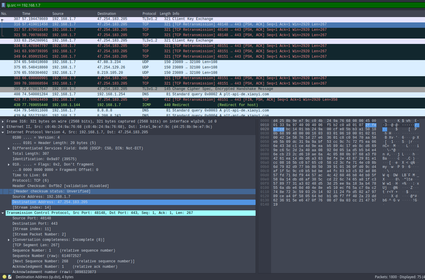
Once the attack is launched, you can start visualizing the network traffic with a packet analyzer (for example Wireshark). You can apply filters to display only packets from a given IP, a specific protocol, or a particular port — very handy for isolating relevant exchanges.
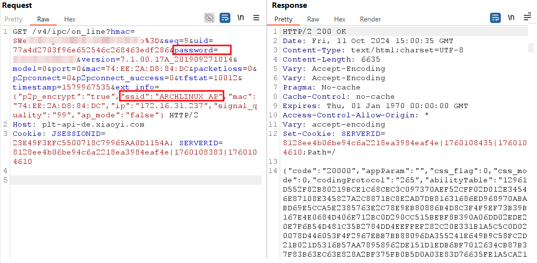
Wireshark tips If it’s your first time with Wireshark or you want to level up, I strongly recommend consulting chapter 7 of the official documentation. It covers advanced filtering and analysis techniques that will save you a lot of time.In our case, placing myself in a MITM position and inspecting the packets with Wireshark, I quickly noticed a large number of outbound HTTP requests. I emphasize that I had only connected the camera to the network: no cloud account creation, no explicit authorization to connect to the service. Despite that, the vast majority of requests targeted IP 47.254.183.205 (domain plt-api-de.xiaoyi.com).
The domain plt-api-de.xiaoyi.com exposes an Apache Tomcat 9.0.40 server (incidentally a version known to have several CVEs). After some enumeration tests, I found an endpoint that, when firmware versions are compatible and a new firmware image is available, allows downloading the latest firmware version. Having such an endpoint is interesting: it could have spared me from dumping the firmware manually (and therefore from having to buy an extra camera just to extract the image). Unfortunately for this analysis there was no new version available (checkout required):
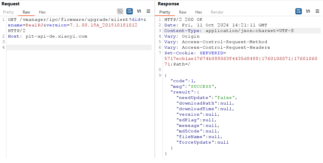
The camera also transmits sensitive information: I observed that it sends the SSID — and even the password — of the Wi-Fi network it is connected to. I am not an IoT product manufacturer, but what functional need does this really serve? What’s the point of transferring these credentials in cleartext to a third-party server? To those concerned, greetings.
Here we want to access the camera’s system to retrieve the firmware or at least obtain a root shell. We have two main approaches: connect via UART (the easiest) and then, if authentication blocks us, force U-Boot to fail to return to its prompt and modify boot parameters.
The first step of the analysis is to disassemble the camera to access its circuit board. The two models examined have an almost identical internal architecture and share most of their components. Once opened, the two boards are displayed side by side:
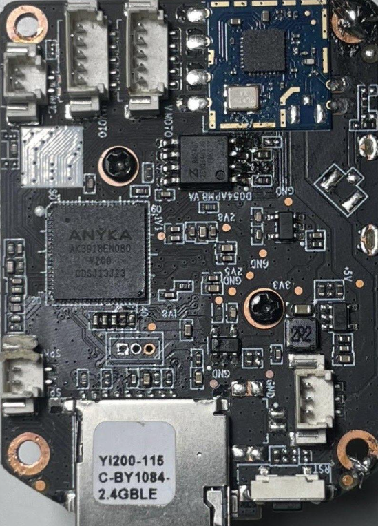 Figure 9 : Camera motherboard (front side)
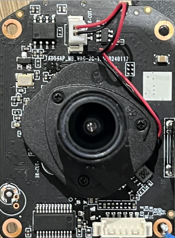 Figure 10 : Camera motherboard (back side)
At the center of the device is the AK3918 SoC, an ARM processor that integrates the watchdog, memory management and several communication interfaces (UART, SPI, JTAG…). This component plays a central role as it aggregates the system’s computation and control functions. Beside it, the SV6256P Wi-Fi module provides wireless connectivity, while the FM25Q64 serial flash stores the firmware and operating system partitions.
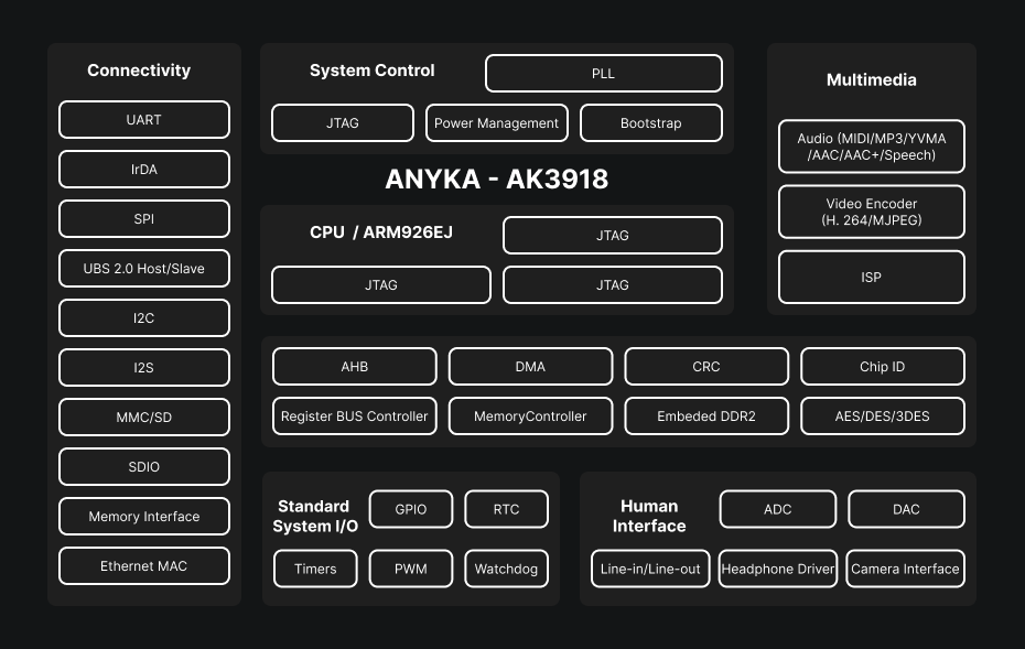
These three elements form the core of the camera: the SoC handles processing and essential peripherals, the Wi-Fi module enables network communication and the SPI flash preserves the software data necessary for boot and operation. The analysis will focus mainly on the SoC and the flash memory, because they offer the most interesting entry points for hardware and software exploitation.
Initial access is performed via the UART (Universal Asynchronous Receiver/Transmitter) interface, an asynchronous serial protocol widely used for debugging embedded systems. We covered this in detail in the Pentest IoT series, which I invite you to consult!
Practical introduction to UART for IoT pentesting: identifying pins, methods (PCB inspection, multimeter, logic analyzer), secure wiring and configuration, and techniques for obtaining a console.
On this board the UART pins are clearly marked, which makes the task easier. Simply connect TX, RX and GND to a USB–UART adapter, then open a terminal like minicom or screen. By trying different speeds, typically 115200 baud, you eventually see the system boot and the U-Boot bootloader appear.
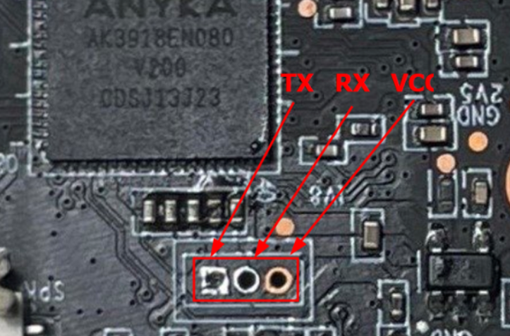
Once connections are in place, a serial terminal is opened with a tool such as minicom or screen. Then you need to determine the device’s baud rate — generally 115200 is a good starting point. A few tries are enough to obtain a readable output: the boot sequence displays, revealing the U-Boot bootloader sequence.
However, access requires a username and password. After trying the usual combinations (root/root, admin/admin, etc.), I didn’t insist further: on this type of cameras, passwords are often generated dynamically at boot or derived from a unique identifier, which makes brute-force attempts rather unproductive.
Because the data rate of a UART connection remains relatively low (a few thousand bytes per second in practice), attempting a brute-force on the root password would have been of little interest, especially since the operation would be extremely long (you might as well read an Intel x86 manual). Rather than waste time on this ineffective approach, it is smarter to focus on the boot process itself. Indeed, intervening at the bootloader level often provides better visibility into the system and can, in some cases, allow obtaining direct shell access without going through the usual authentication phase.
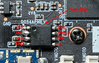
On a typical SPI serial flash, the main signals are: CS# (chip select), CLK (clock), DI / MOSI (Master Out — Slave In), DO / MISO (Master In — Slave Out) — and sometimes extra lines in Quad-SPI mode (IO0..IO3). The pin often named D0 typically corresponds to the DO / MISO line: it is the path by which the flash memory sends bytes to the controller (the “master,” here the SoC) during a read. The controller generates the clocks (CLK) and the flash responds on DO with the requested data.
The bootloader follows a simple, strict sequence: it orders a read from the flash (via SPI), reads a certain number of bytes, computes or verifies a checksum/CRC, then decides if the image is valid before loading/executing it. If, at read time, the DO line provides incorrect, incomplete or inconsistent bytes (for example repeated zeros), then the data received by the master will not match the expected image. The integrity check (CRC) fails and the bootloader signals an error — hence the “Bad Data CRC” message — and, by design for robustness, it will not execute a potentially corrupted kernel.
In other words, short-circuiting the flash’s outgoing data path at read time logically “renders the partition unreadable.” The bootloader then reacts as expected: it halts the normal sequence and falls back into an investigative mode (prompt, errors, logs) instead of executing something uncertain.
Once at the bootloader prompt, it is possible to bypass the login screen by modifying the bootargs environment variable. These arguments are passed to the Linux kernel at boot and define its behavior: the serial console, the root partition, the filesystem type, the init process, available memory, etc.
Codeanyka$ printenv
backuppage=ffffffff
baudrate=115200
boot_normal=readcfg; run read_kernel; bootm ${loadaddr}
bootargs=console=ttySAK0,115200n8 root=/dev/mtdblock4 rootfstype=squashfs init=/sbin/init mem=64M memsize=64M
bootcmd=run boot_normal
bootdelay=0
console=ttySAK0,115200n8
erase_env=sf probe 0:0 ${sf_hz} 0; sf erase 0x20000 0x2000
ethaddr=00:55:7b:b5:7d:f7
fs_addr=0x230000
init=/sbin/init
ipaddr=192.168.1.99
kernel_addr=31000
kernel_size=159f88
loadaddr=81808000
memsize=64M
mtd_root=/dev/mtdblock4
netmask=255.255.255.0
read_kernel=sf probe 0:0 ${sf_hz} 0; sf read ${loadaddr} ${kernel_addr} ${kernel_size}
rootfstype=squashfs
serverip=192.168.1.1
setcmd=setenv bootargs console=${console} root=${mtd_root} rootfstype=${rootfstype} init=${init} mem=${memsize}
sf_hz=20000000
stderr=serial
stdin=serial
stdout=serial
update_flag=0
ver=U-Boot 2013.10.0-AK_V2.0.04 (Jun 05 2023 - 14:05:38)
vram=12M

Environment size: 950/4088 bytes
Looking at the printenv output, we see that init= points to /sbin/init, the usual init binary. By replacing it with /bin/sh, the system boots straight to a root shell.
Codeanyka$ setenv bootargs console=ttySAK0,115200n8 root=/dev/mtdblock4 rootfstype=squashfs init=/bin/sh mem=64M memsize=64M<
anyka$ run bootcmd
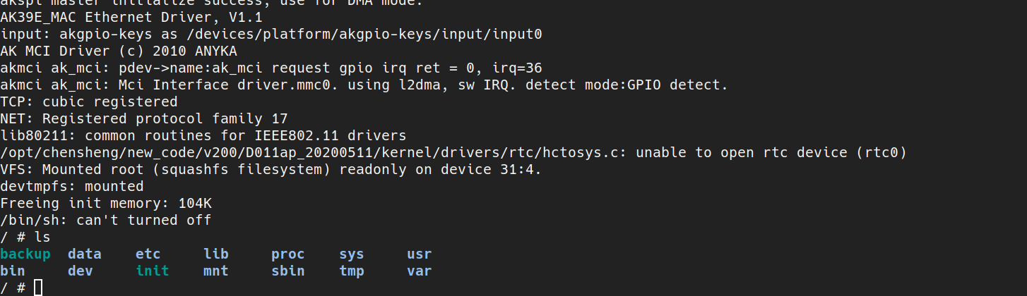
The result is immediate: the system initializes with a root shell, offering full access as soon as it boots. In the context of this lab, it’s a simple and effective way to explore the firmware and test critical functionality.
As you may have guessed, keeping the same setup to get a shell on the camera is cumbersome and heavy. The goal is to get rid of that: to be able to access the camera directly without shorting the flash chip, modifying boot arguments, manually mounting files, etc.
To do that, we will try to implant some form of persistence (retrieve a password, keep an access, …) or upload a backdoor that bypasses the initial authentication.
Note: at initial boot, just after modifying the boot arguments,/etc/passwd and /etc/shadow are empty, which is normal because they are not yet mounted. There are therefore no exploitable accounts at this stage; these files need to be mounted.
Reminder: we modified the init attribute to point to /bin/sh. Originally U-Boot passed init=/sbin/init. /sbin/init is actually a symlink to BusyBox:
Codeanyka$> ls -la /sbin/init
lrwxrwxrwx 1 1012 1013 14 Jun 21 2018 /sbin/init -> ../bin/busybox
BusyBox then runs the init script /etc/inittab, which calls /etc/init.d/rcS. The latter mounts filesystems and notably executes:
/etc/init.d/rc.local/bin/mount -t squashfs /dev/mtdblock5 /usr
/bin/mount -t jffs2  /dev/mtdblock6 /etc/jffs2
/bin/mount -t jffs2  /dev/mtdblock7 /data
The script /etc/init.d/rc.local mounts several partitions, including the JFFS2 that contains the persistent configuration: as long as /dev/mtdblock6 is not mounted on /etc/jffs2, /etc/passwd and /etc/shadow are missing or empty — once the mount is performed, the JFFS2 partition provides these system files and the accounts become available.
Codeanyka$> cat /etc/passwd
root:...:0:0:root:/:/bin/sh
daemon:...

anyka$> cat /etc/shadow
root:$1$...:0:0:99999:7:::
So we can modify the root account password, reboot the camera and connect directly. And thus, legitimately, a root shell.